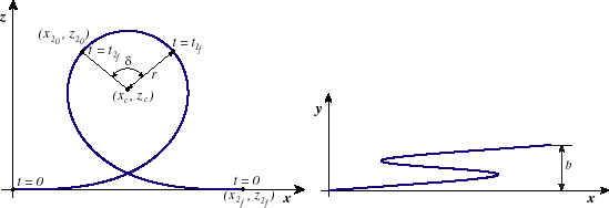
A loop is used to turn riders upside down. The clothoid loop is an element that can easily be identified on many roller coasters by its ``teardrop'' shape, with a tight radius at the top and a looser radius toward the bottom, which is used is to control the forces on a passenger. Centripetal force is stronger at higher curvature and higher velocities. A clothoid loop was chosen because when higher velocities are encountered (at the bottom of the loop), the curvature is very small. It also conveniently results in continuous curvature, a primary goal of this research.
A loop is located primarily in the ![]() -
-![]() plane, with a small component in the
plane, with a small component in the ![]() direction, to
allow the track to shift over enough to pass itself on the way down. A loop can be described with
three parameters, described below and depicted in figure 2.5.
direction, to
allow the track to shift over enough to pass itself on the way down. A loop can be described with
three parameters, described below and depicted in figure 2.5.

|
The loop should be nearly planar, leaving only enough clearance to allow a car to safely pass through the loop. If a loop with more shift separation is desired, a corkscrew2.5 may better suit the design requirements.
While the circular region of a loop need not exist, there is good reason to include it. This becomes clear when modeling a train, instead of simply a car. The elevation at the top of the loop is higher with a circular region than it would be without one, since the curvature would continue to increase with a clothoid, pulling the top of the loop downward. As the train navigates the loop, its center of gravity does not follow the path of the loop, but is below the track as the train approaches the top. If no circular region is used, the center of gravity of the train will actually drop as the center of the train approaches the top of the loop, resulting in a speed increase. One of the purposes of using the clothoid in a loop is to control the centripetal forces, putting the highest curvature regions where the lowest speeds are expected to be attained, at the top of the loop. But if the center of gravity of the train drops, the speed will actually increase as the highest curvature region is navigated. Therefore a circular region is used at the top of the loop to keep the center of gravity of the train from dropping as the high curvature region is navigated.
A loop is created in nearly the same manner as a curve. The biggest difference is that the
circle/clothoid projection lies in the ![]() -
-![]() plane for a curve, and in the
plane for a curve, and in the ![]() -
-![]() plane for a
loop. As with a curve, a loop is created by first determining the coordinates of the projection in
this plane from the clothoid parameters. The constant shift angle (as opposed to the vertical
angle for a curve) is then calculated from the shift separation,
plane for a
loop. As with a curve, a loop is created by first determining the coordinates of the projection in
this plane from the clothoid parameters. The constant shift angle (as opposed to the vertical
angle for a curve) is then calculated from the shift separation, ![]() . The shift change (
. The shift change (![]() coordinate) is linear with respect to arclength along the loop.
coordinate) is linear with respect to arclength along the loop.
The clothoid parameters are calculated in the same manner as for a curve. Refer to section
2.1.2. The projected length of a loop in the ![]() -
-![]() plane is then found from the equations
for the arclength of a clothoid and of a circle.
plane is then found from the equations
for the arclength of a clothoid and of a circle.


|

 |
(2.51) |
The initial and final vertical angles of a loop are both zero by definition, which is admittedly a
limitation of the definition of a loop. More advanced techniques should ideally be used to allow
a loop to begin at a non-zero slope and curvature, but that is beyond the scope of this research.
 |
(2.52) |
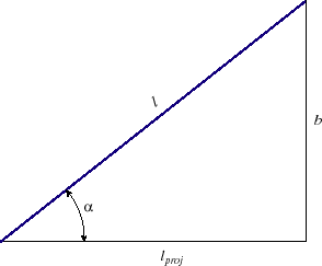
In order to calculate the required geometric functions of a loop, the projected arclength in the ![]() -
-![]() plane,
plane, ![]() , will be used instead of the arclength along the loop,
, will be used instead of the arclength along the loop, ![]() . The conversion is made with the following, which can be inferred from figure 2.6.
. The conversion is made with the following, which can be inferred from figure 2.6.
