

Next: Clothoid 1:
Up: Elements
Previous: Straight Elements
Contents
Curve Elements
A curve is used to turn the track in the  -
- plane. It can also have a vertical component
which moves the rider up or down while traversing the curve. As explained in section
2.1, a curve is a clothoidal element, meaning that it is made up of an entrance
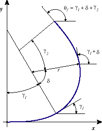
clothoid, a circular region, and an exit clothoid. These regions can be seen in figure
2.2. A curve can be specified with six parameters which are described below. Many
of these parameters are illustrated in the figure.
Figure 2.2: Curve Element Parameters.
The projection of the curve in the
 -
- plane is shown, illustrating the circular and clothoidal regions. The minimum radius of a curve, as well as the circular and clothoid angles, are depicted here.

|
- direction
- Specifies whether the track is to turn left or right relative to the forward
direction upon entering the curve.
- radius

- The minimum radius of the curve. This is the constant radius of
curvature in the circular region of the
 -
- projection of the curve. (
 )
)
- entrance clothoid angle

- Clothoid 1 is the region in which the
curvature varies from zero to
 . The azimuth angle change experienced by the car as it
traverses clothoid 1 is
  . This angle must be greater than zero to guarantee
curvature continuity. (
 )
)
- circular curve angle

- The angle of the curve with radius
 . The car
undergoes an azimuth angle change of
  in this region. No circular region is required for a
curve element. (
 )
)
- exit clothoid angle

- Clothoid 2 is the region in which the
curvature varies from
 back to zero. The azimuth angle change experienced by the car as it
traverses clothoid 2 is
  . This angle must be greater than zero to guarantee
curvature continuity. (
 )
)
- height

- The elevation change of the curve from beginning to end.
To determine the equations of a curve, the  -
- projection is first created from
  ,
,  ,
,  , and
, and  . The arclength of the
  -
- projection and the height,
  , are then used to calculate the vertical angle, defined to be constant throughout the curve. The height change throughout the curve is therefore linear with respect to arclength along the curve.
In order to describe the clothoid regions of the curve, the scaling parameters,  and
and
 , as well as the range of the variable
  for each clothoid, need to be determined.2.3 Both the entrance and exit clothoid
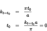
have zero curvature at the end of the curve element. The variable
  will be defined to be
 at that end. The following can be found from equation A.6.
The azimuth angle change of the curve through a clothoid region is given by  . This
can be used to determine the final value of the variable
  . See equation A.7.
The clothoid scaling parameter can now be found from the value of  and equation
A.6. The junction of the clothoid and the circular region occurs when
  . The
curvature is
  at this point.
The arclength of a clothoid is given by equation A.5.
The length of the projected curve in the  -
- plane is found from the equations for the
arclength of the clothoids and of the circle.
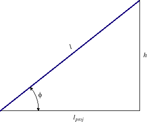
Figure 2.3: Curve Vertical Angle.
This figure illustrates the relationship between the total length of the curve, the length of the projection in the
 -
- plane, and the elevation change. Note that
 is a constant angle throughout the curve, as explained in section 2.1.

|
The vertical angle,  , is depicted in figure 2.3. The hypotenuse in the figure
represents the total length of the curve. The lower leg, labeled
  , represents the length
of the projection of the curve in the
  -
- plane. The angle
  can therefore be found from the
following.
The initial and final vertical angles are both  , as the vertical slope does not change
throughout a curve element.
 |
(2.18) |
The total arclength of the curve is found from the Pythagorean Theorem, since it can be viewed
as the hypotenuse of a right triangle. The legs are the height and the length of the projection of the curve in the  -
- plane.
 |
(2.19) |
The azimuth angle change a car undergoes is the rotation its forward vector experiences. In a
curve element, the azimuth angle change through clothoid 1 is  . Through the
circular region the car rotates
  and through clothoid 2 the rotation is
  . The
total curve angle is given by
  , which is the azimuth angle at the end of the curve.
 |
(2.20) |
Recall that the required geometric functions of an element are the position vector,
 , the forward and radial vectors,
 and
and
 , and the curvature,
  . In order to calculate these functions for a curve, the projected arclength in the
  -
- plane,
  , will be used instead of the arclength along the curve,
  . The conversion is made with the following, which can be inferred from figure 2.3.
The equations of the curve are derived assuming a left-hand turn. If it is a right-hand turn, the curve will be a mirror image of the one calculated. Since the initial forward direction is in the  -
- plane, all that must be done is to negate the values of
  , thereby producing the mirror image.
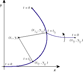
Figure 2.4 illustrates the construction of a curve, and labels many of the
coordinates that will be discussed.
Figure 2.4: Curve Construction.
This figure illustrates how a curve is created. First clothoid 1 is created, beginning at the origin with
 .
The end of clothoid 1 occurs when
 ,
at
,
at
 .
The center of the circular region,
 ,
can then be found. The circular region is added, beginning where clothoid 1 ended. The beginning of clothoid 2,
 ,
is then found. Since clothoid 2 starts with non-zero curvature,
 at the beginning of the clothoid and
 at the end. The clothoid is inially created such that it ends horizontally, and is then rotated
 radians about the
 axis to line up the azimuth angle at the beginning of clothoid 2 with the azimuth angle at the end of the circular region.

|
2.3
See appendix
A for a complete description of clothoids.
Subsections


Next: Clothoid 1:
Up: Elements
Previous: Straight Elements
Contents
Darla Weiss
2000-02-13
![]() -
-![]() plane. It can also have a vertical component
which moves the rider up or down while traversing the curve. As explained in section
2.1, a curve is a clothoidal element, meaning that it is made up of an entrance
clothoid, a circular region, and an exit clothoid. These regions can be seen in figure
2.2. A curve can be specified with six parameters which are described below. Many
of these parameters are illustrated in the figure.
plane. It can also have a vertical component
which moves the rider up or down while traversing the curve. As explained in section
2.1, a curve is a clothoidal element, meaning that it is made up of an entrance
clothoid, a circular region, and an exit clothoid. These regions can be seen in figure
2.2. A curve can be specified with six parameters which are described below. Many
of these parameters are illustrated in the figure.

![]() -
-![]() projection is first created from
projection is first created from ![]() ,
, ![]() ,
, ![]() , and
, and ![]() . The arclength of the
. The arclength of the ![]() -
-![]() projection and the height,
projection and the height, ![]() , are then used to calculate the vertical angle, defined to be constant throughout the curve. The height change throughout the curve is therefore linear with respect to arclength along the curve.
, are then used to calculate the vertical angle, defined to be constant throughout the curve. The height change throughout the curve is therefore linear with respect to arclength along the curve.
![]() and
and
![]() , as well as the range of the variable
, as well as the range of the variable ![]() for each clothoid, need to be determined.2.3 Both the entrance and exit clothoid
have zero curvature at the end of the curve element. The variable
for each clothoid, need to be determined.2.3 Both the entrance and exit clothoid
have zero curvature at the end of the curve element. The variable ![]() will be defined to be
will be defined to be
![]() at that end. The following can be found from equation A.6.
at that end. The following can be found from equation A.6.


![]() -
-![]() plane.
plane.

![]() . Through the
circular region the car rotates
. Through the
circular region the car rotates ![]() and through clothoid 2 the rotation is
and through clothoid 2 the rotation is ![]() . The
total curve angle is given by
. The
total curve angle is given by ![]() , which is the azimuth angle at the end of the curve.
, which is the azimuth angle at the end of the curve.

![]() , the forward and radial vectors,
, the forward and radial vectors,
![]() and
and
![]() , and the curvature,
, and the curvature, ![]() . In order to calculate these functions for a curve, the projected arclength in the
. In order to calculate these functions for a curve, the projected arclength in the ![]() -
-![]() plane,
plane, ![]() , will be used instead of the arclength along the curve,
, will be used instead of the arclength along the curve, ![]() . The conversion is made with the following, which can be inferred from figure 2.3.
. The conversion is made with the following, which can be inferred from figure 2.3.

![]() -
-![]() plane, all that must be done is to negate the values of
plane, all that must be done is to negate the values of ![]() , thereby producing the mirror image.
, thereby producing the mirror image.
